Newest progress reports are at the bottom of the page
I will try and update this page with new photos at least every 3-4 days. The date at the end of the caption is when the photo was uploaded. The actual progress of the layout is a little ahead of what you see here.
May - August 2010
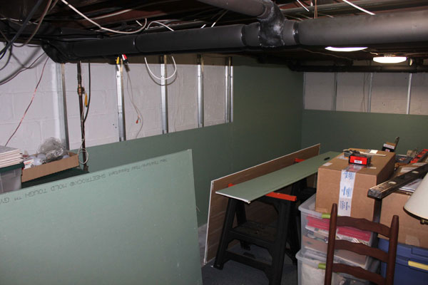
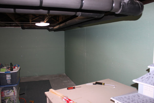
The basement in my house needed to be finished first before the layout could be built. Sheetrock on metal studs cover the 85 year old concrete block walls. (5/14/10)
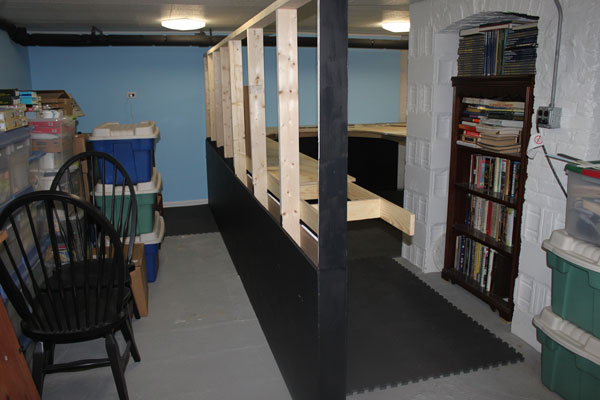
Another view of the 25×25 foot basement getting a makeover. The CF lighting was also added. To the right is the chimney foundation in the center of the basement. (5/14/10)
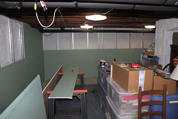
The area at the bottom of the photo is where the Bay Head loop and yard is planned. My track plan is a little non-conventional, with the end of the line located in the middle of the layout. (5/14/10)
I used metal studs over concrete block painted with a waterproofing paint. The sheetrock is a mildew resistant type. Luckily, the basement has always been dry. (5/14/10)
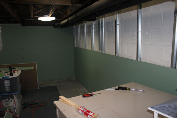
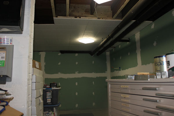
Sheet rock is up...taping is next. The insulated heating pipes are about 78 inches from the floor. The bottom of the ceiling joists average around 7 feet from the concrete floor. (5/17/10)
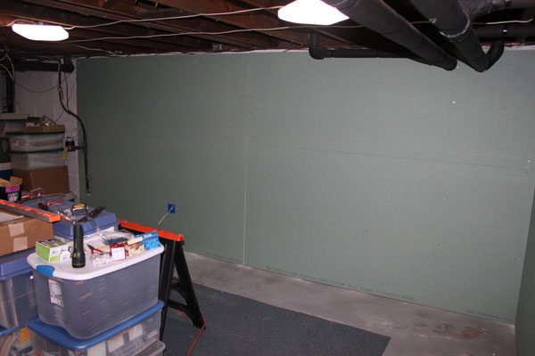
Electric outlets were strategically placed along the new walls based on the proposed layout plan. Of course, it probably won't be enough when all is said and done! (5/17/10)
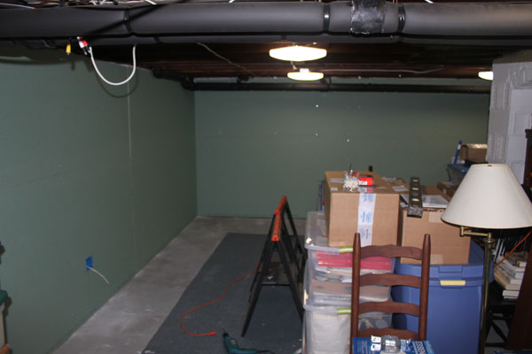
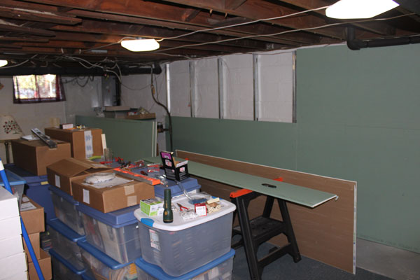
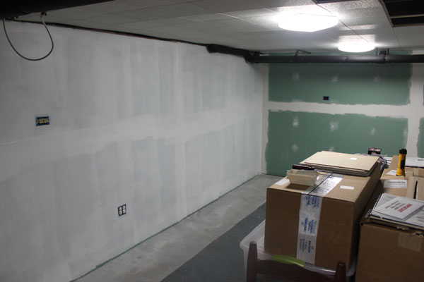
Another view of the south half of the basement. Stairway behind the camera. (5/20/10)
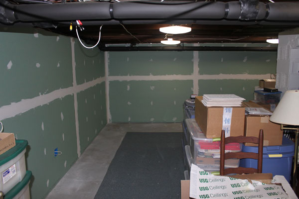
Tape, mud and a lot of sanding. The shop-vac was never far away during this phase. (5/20/10)
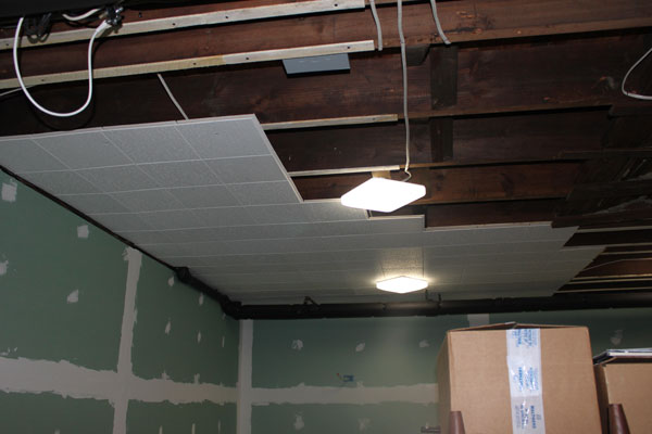
Work begins on the ceiling. Furring strips are attached to the bottom of the joists to allow the passage of existing wires. I used 12x12 inch USG interlocking tiles. (5/23/10)
The tiles were screwed and stapled to the strips. The ceiling is imperative for good lighting and to keep dust and dirt from falling onto the layout from above. (5/23/10)
While the ceiling was going up, the walls got a primer coat of paint, followed by two coats of sky blue flat latex paint. The electrical work was also finished up at this time. My biggest problem now was finding a workable solution to store the many boxes and bins in my way! (5/26/10)
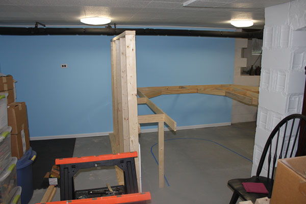
The walls and ceiling are done and the floor/ceiling trim is up. The next phase begins with construction of the center partition and the beginning framing for the layout. Note the tape on the floor. Also experimenting with interlocking floor mats (left) on the concrete floor slab. (5/26/10)
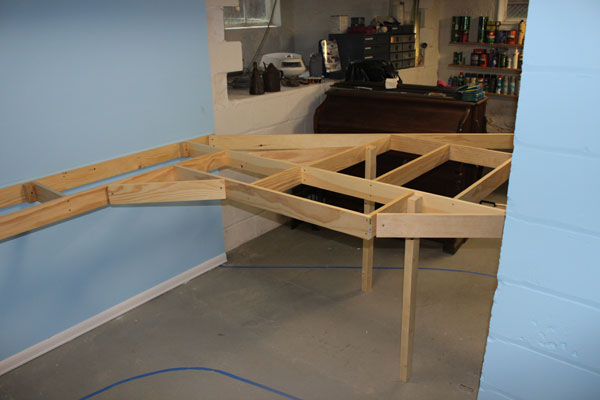
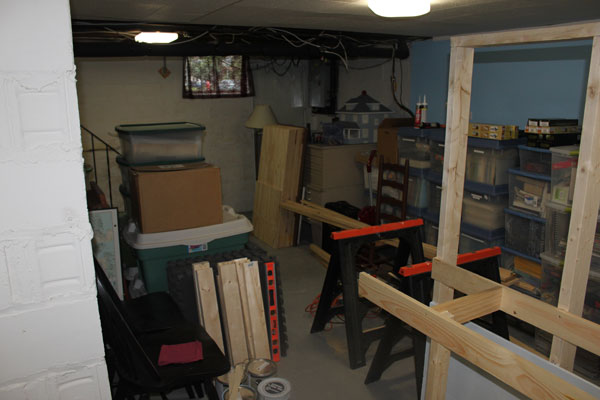
The bench work for the Bay Head loop and yard takes form. I roughly marked out the edges of the layout on the floor using a scale mockup of the yard which I had drawn on large rolls of paper taped together. The old pump organ in the background was moved to the garage. Any takers? (5/29/10)
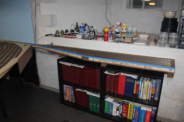
I used 1x4 lumber for the bench work, glued and screwed together with deck screws. In the background is the other half of the basement and my work shop and bench. It's kind of hard keeping things neat and tidy with a project like this going on! (5/29/10)
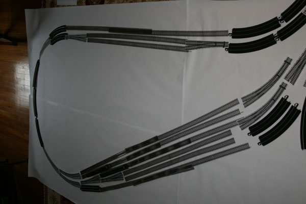
Here are a couple of shots from the initial planning stages showing how I laid out the Bay Head loop portion of the layout. I used anything I could find spread out over large sheets of paper to help determine the size of what I wanted to model and what would actually fit. (6/1/10)
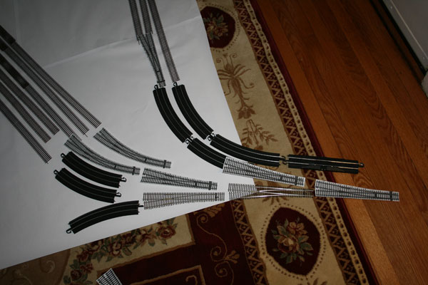
Actual track and turnouts, as well as photocopies of turnouts were used. Once I was satisfied, I traced the loop and yard onto the paper. This shot shows the mock-up of the entrance to the loop and coach yard from the double-track main line. (6/1/10)
A basement can get a bit messy when building a model railroad. (6/1/10)
The boxes on the left contain some of the locos and rolling stock for the layout. (6/1/10)
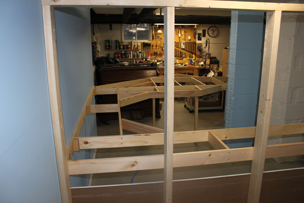
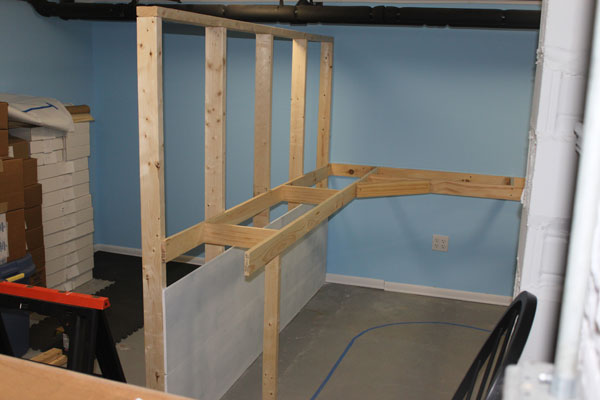
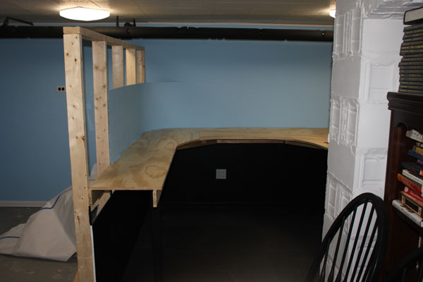
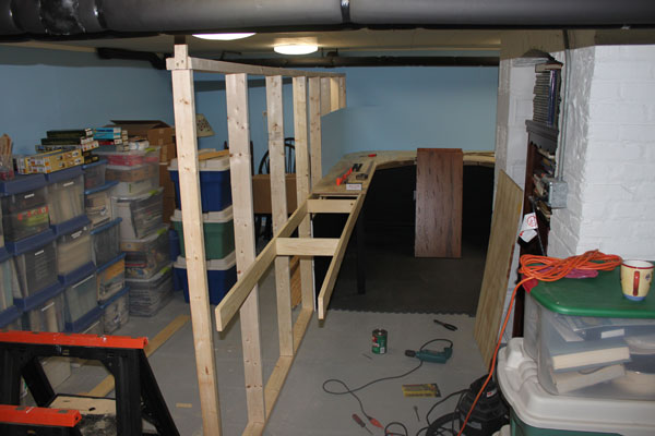
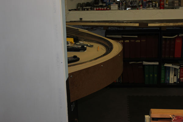
When designing the layout, I needed to have access to both sides of the Bay Head Junction and loop portion of the line. That required me to place this end of the line in the center of the room. I constructed the wall on the left to support the far end of the loop. (6/4/10)

The small wall also served to hide the house mechanicals...namely the oil furnace and gas hot water heater. Numerous plastic bins hold and protect what will eventually be incorporated in to the layout as it grows. (6/4/10)
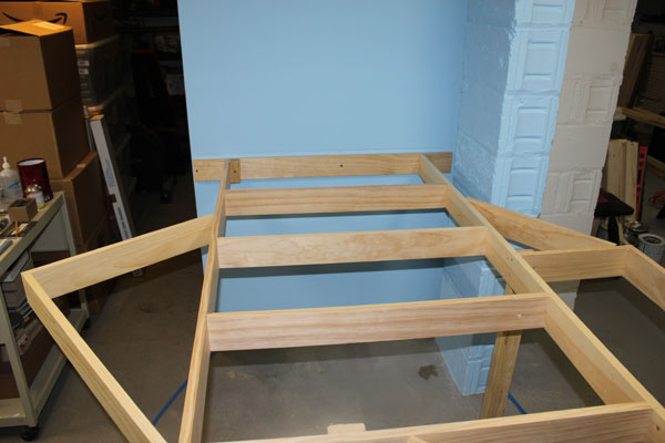
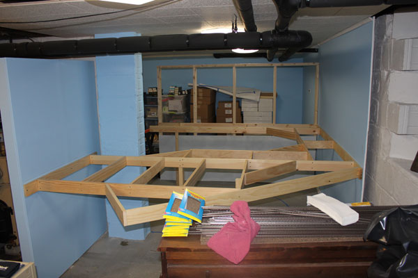
Simple but sturdy bench work for the Bay Head Yard. (6/4/10)
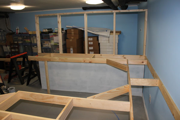
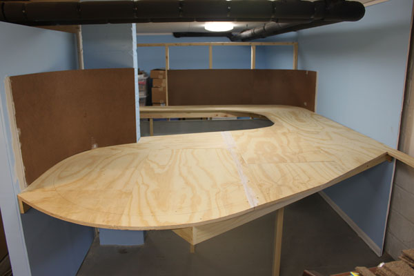
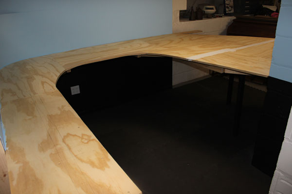
Another view. The 3/4 inch plywood top is ready to be installed in this section. (6/4/10)
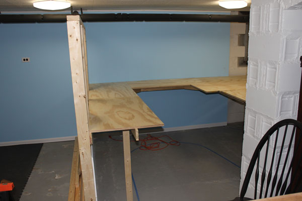
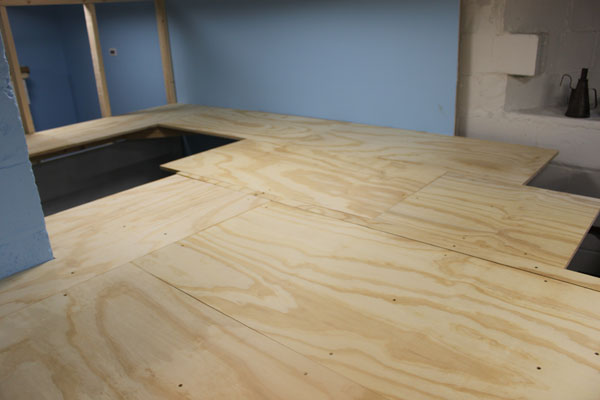
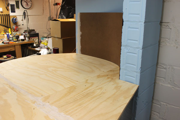
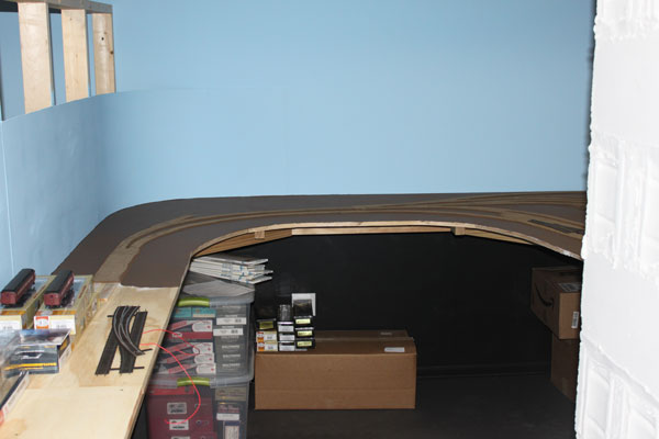
I next laid 2x4 foot sheets of 3/4 inch plywood onto the bench work, making sure that it extended beyond the proposed edge of the layout as marked on the floor. (6/7/10)
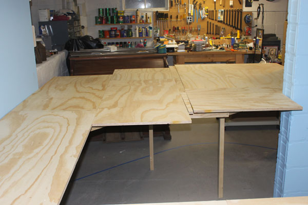
I really didn't have any means to get full 4x8 sheets of plywood to my house, outside of delivery, let alone getting them down into the basement. The half-size sheets had to do. (6/7/10)
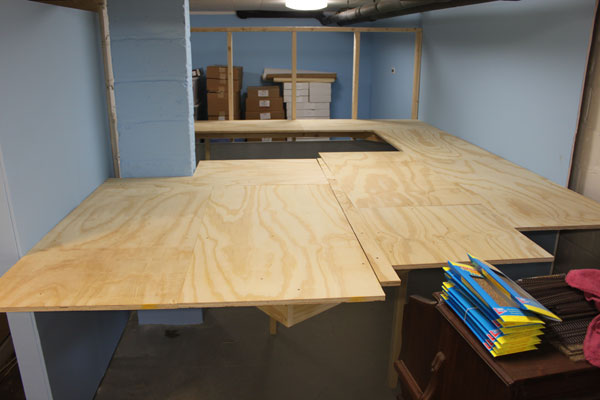
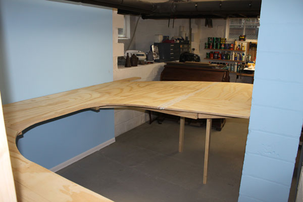
Once I was satisfied with everything, I removed the plywood and installed each sheet using carpenter's glue and deck screws. (6/7/10)
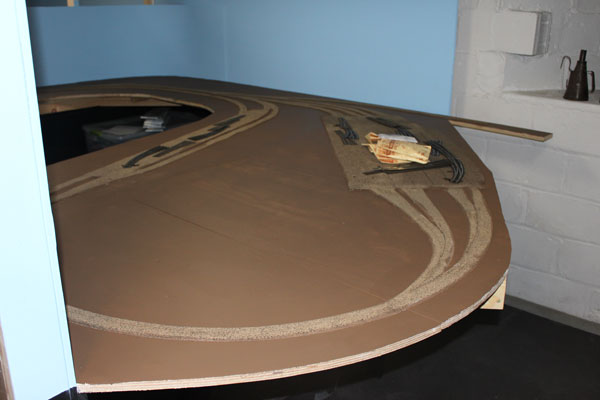
I was quite satisfied with the way the top ended up. Everything checked out as being level. This is where the Bay Head loop and coach yard will be located. (6/7/10)
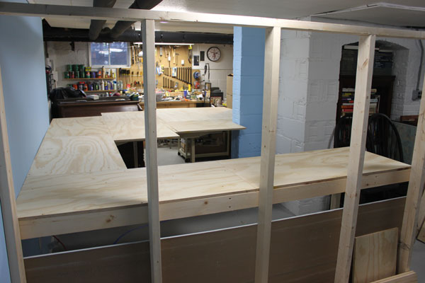
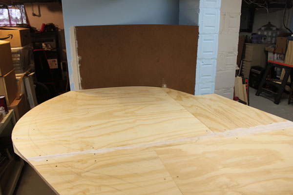
With the plywood top secured, the next step was to mark off where the edges of the layout were to be cut off. (6/7/10)
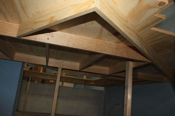
An underneath view of the Bay Head Yard section of the layout. By this point, I really felt a sense of progress with the layout. Marking the tracks was the next fun step! (6/7/10)
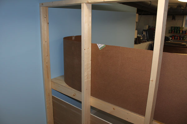
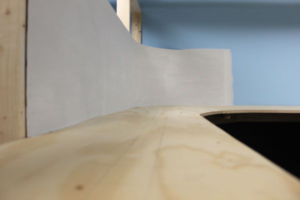
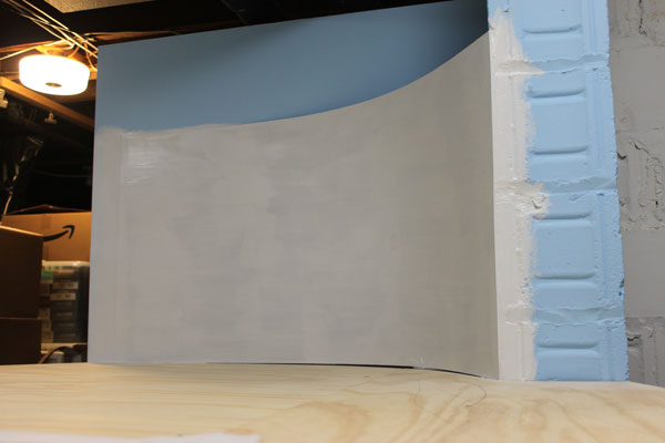
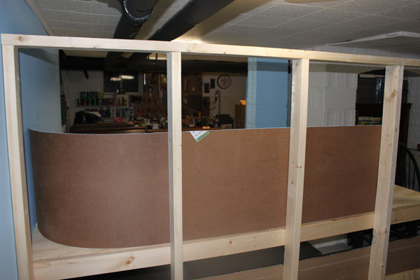
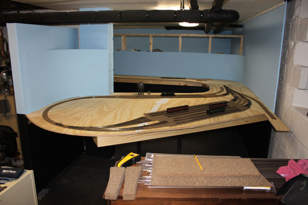
1/8 inch hardboard is installed along the peninsula for the backdrop. It's pretty easy to work with and easy to cut and bend. (6/10/10)
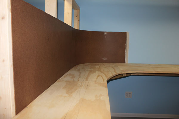
The front side is glassy-smooth and works well with spackle or sheet rock compound to blend in the splices or ends. (6/10/10)
A backdrop was also installed along the rear of the Bay Head loop track which flows along with the curving track. (6/10/10)
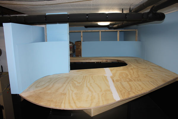
Well, the plywood has been secured to the bench work and the borders have been trimmed according to my layout plans. The old, heavy organ is still in the way, though! (6/10/10)
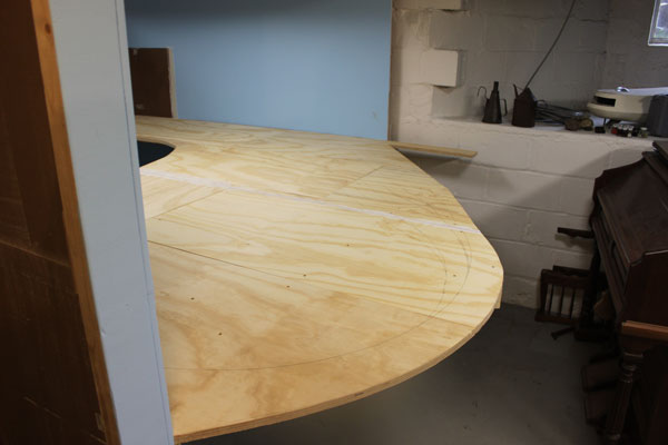
Before trimming the plywood top, I marked approx. where the tracks would be located. The protrusion in the upper center is for a lead into a staging yard. (6/10/10)
Another view of the backdrops at BH Junction. The lead into staging to the right actually models the PRR Atlantic Division Line south to Seaside and then west to Pemberton, NJ. (6/10/10)
The completed bench work at Bay Head Junction. At this point, I was seriously thinking roadbed and track work. (6/10/10)
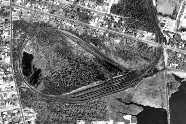
This is an aerial of the Bay Head loop in 1962. The engine servicing tracks are to the top, while the coach yard is to the bottom. The PRR line south to Seaside is on the right. North is top. (6/10/10)
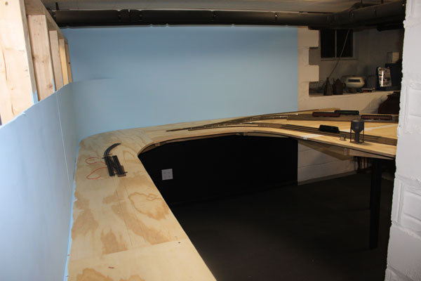
The backdrop next needed to be primed with two coats. (6/14/10)
Primer was then followed by two coats of sky blue. The loop backdrop here. (6/14/10)
Once painted blue, the backdrops blended in quite well with the painted drywall. (6/14/10)
Note that I also painted the walls under the layout flat black. (6/14/10)
Since my basement climate is very well controlled, I left the rear of the hardboard unpainted. (6/14/10)
The black floor tiles and black walls under the layout keeps the focus on the layout and not underneath. The fascia will also be painted flat black. (6/14/10)
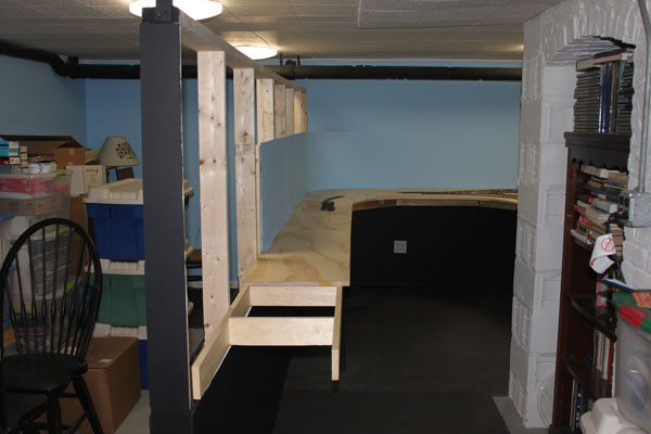
I was now ready to extend the center peninsula partition to its full length of 16 feet, shown here. A 180 degree turn will bring the mainline back on the other side, both levels. (6/18/10)
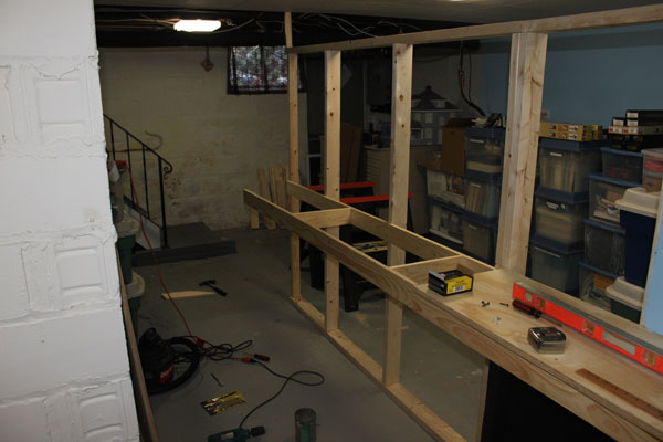
Tools, wood, sawdust, storage bins everywhere! I'm still grappling with what to do with everything as the layout encroaches. At least the pump organ is now in the garage! (6/18/10)
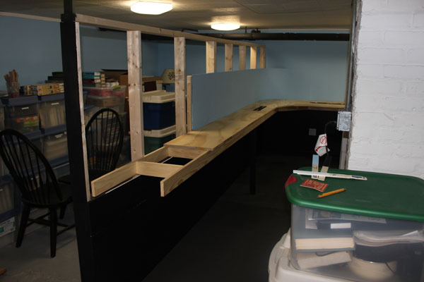
The plywood top and backdrop is now extended, as well as the painted drywall underneath. The Bay Head crossover can be spotted on the deck (fast tracks model). (6/18/10)
Since I still had some leftover drywall from the original wall construction, I attached it to the center wall and painted it as well. One less step to do later on, I guess. (6/18/10)
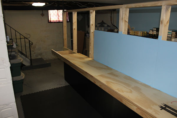
After the Bay Head Junction crossover (right), this part of the lower level of the layout will model the approach to the Point Pleasant Beach station which will be past the 180 degree turn. A lot of grade crossings are here including a siding to Makin Concrete Block Manufacturing. (6/18/10)
An early 1950s view of the Bay Head Yard. The track on the extreme left is the loop running track. To the right is the west-bound loop entrance track next to the two, to eventually, three engine servicing tracks. Note the high-level switch stands which will be modeled. (6/18/10)
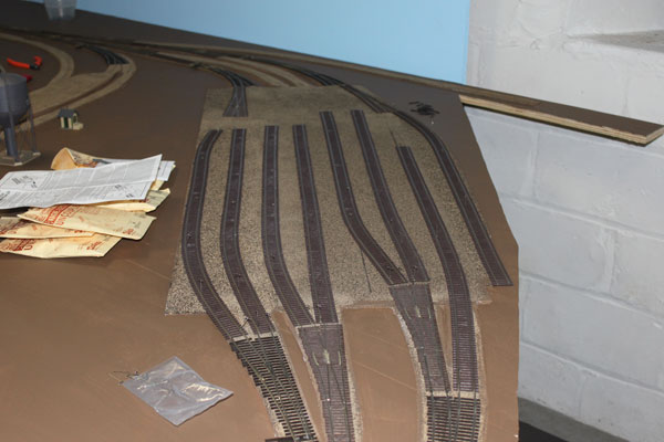
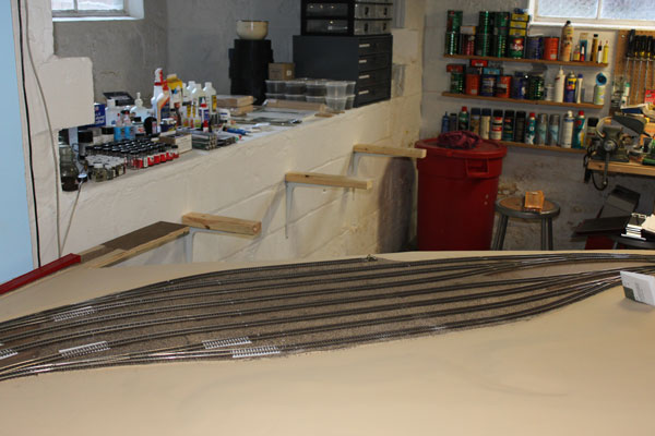
Track laying (or roadbed work), has started on the HO NY&LB. Cork pads go down in the Coach Yard at Bay Head Junction with test track laying on top. The real yard here is only a few feet above sea level. (6/21/10)
I glued the cork down using adhesive caulk and pinned it to the plywood sub-roadbed until it dried. I used the many curved turnouts needed here as templates with track centers at 2.5 inches since there is frequent coupling/uncoupling in this yard. (to accommodate fat fingers) (6/21/10)
Because of space constraints, my Bay Head Yard uses a number of curved turnouts to make it work. Not my favorite choice...but hopefully not a future headache. (6/21/10)
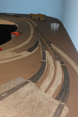
Another view of the line exiting Bay Head Junction and running Eastbound (geographic north) into Point Pleasant Beach. (6/21/10)
I kept the radius of the track to 24 inches or greater...except at the entrance to the engine servicing yard, where the radius is about 20 inches. The prototype is REALLY tight as well. The squealing flanges were very loud when a 4-6-2 k4s rounded the bend! (6/21/10)
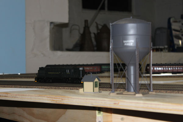
The actual loop or balloon track has a radius of 26 inches with a slightly banked track. Here, a PRR RS11 sits on the temporary track. The Alco diesel, as well as the water tank, will not be part of the yard when operational! (6/21/10)
I used Midwest split Ho cork roadbed which was easy to work with. I used Midwest pre-made turnout roadbed where I could, otherwise they were hand made. (6/25/10)
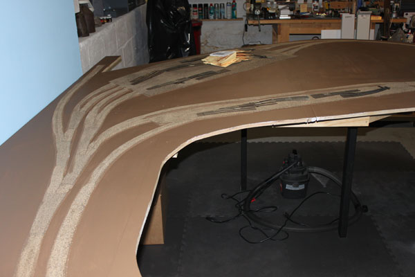
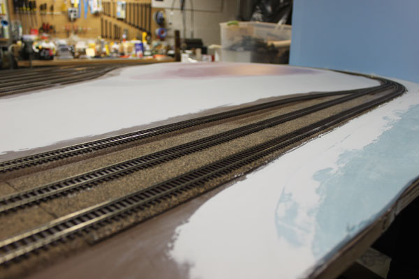
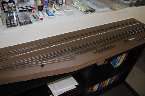
Once all of the roadbed had dried, I sanded the sharp edges using a sanding block, cleaned up the mess and painted the plywood top with a dark earth brown latex paint. (6/25/10)
I wasn't too concerned with the color being too dark because all of it was going to be either covered with foam or re-painted a lighter tan color. At least the wood was sealed. (6/25/10)
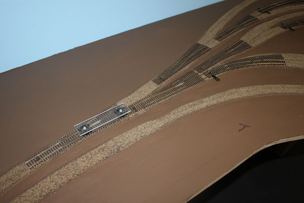
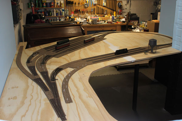
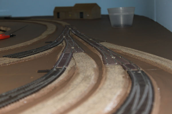
Next came the positioning of the various turnouts and making sure all of the roadbed was where it was supposed to be. I did have to cut and modify roadbed in a few spots. (6/25/10)
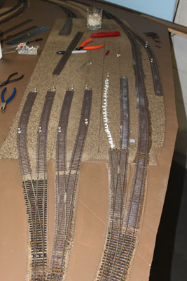
The straight turnouts in the yard are Micro Engineering Code 83 #6. The curved turnouts are Walthers Code 83 ranging from #6.5 to #10. (6/25/10)
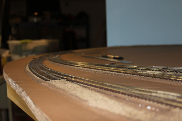
A track level view of the coach yard entrance. I found slight differences in rail height between the Atlas track, ME turnouts and Walthers turnouts which added a bit more work that I expected.
The track configuration at the exit from the coach yard. It looks like some of the rails will need to be filed level at the joints and then polished so they don't attract a buildup of dirt. (6/25/10)
I used pins to position the flex track in the coach yard to check alignments. On the left are the Kadee electromagnetic uncoupling units to be installed. (6/25/10)
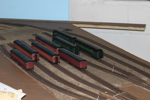
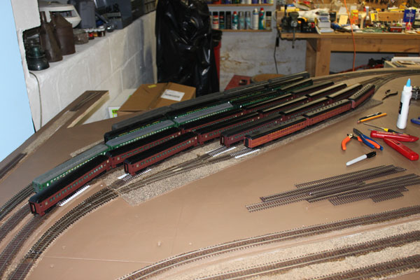
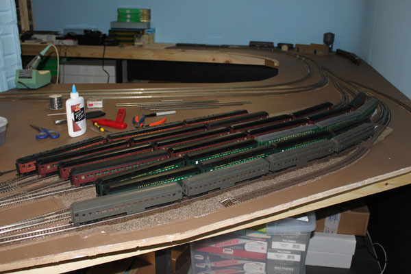
With the coach yard tracks pinned down using T pins, I placed some coaches on the tracks to check the clearances. The tracks here are spaced 2.5 inches apart to accommodate the long coaches. The real yard has VERY tight track spacing. (6/30/10)
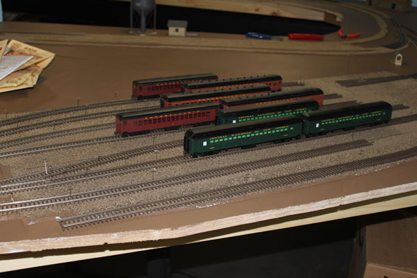
The CNJ coaches here are Bethlehem kits while the PRR cars are a mix of old Bachmann P70 coaches and ConCor P54 cars, which will be confined to the other end of the layout in the electrified territory at South Amboy. (6/30/10)
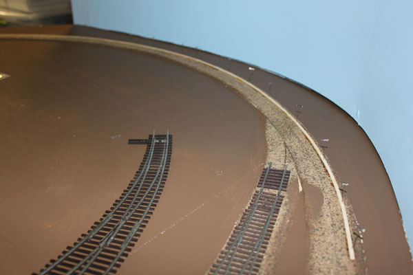
Before laying track on the balloon track, I needed to shim the track to create a slight bank. I used 1/16 inch strip wood glued and pinned to the cork roadbed. I then feathered each end with a sanding block. (6/30/10)
I then glued the flex track down and installed the curved turnouts coming into and out of the curve. The resulting track work ended up being quite smooth, even through the turnouts where the bank transitioned to level track. (6/30/10)
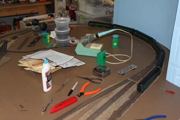
I used anything I could get my hands on to weigh down the track until it was dry. The Chinese food containers hold ME wood ties which were used to fill in the gaps between track sections. (6/30/10)
This view of the banked balloon track shows the effectiveness of banking curves to provide more realism. (6/30/10)
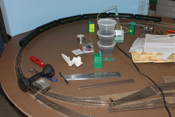
The adhesive caulk is spread out thinly over the cork roadbed prior to laying the track and turnouts. The caulk will become transparent when it dries. (7/4/10)
The track in the coach yard is being glued down using the adhesive caulk (DAP clear kitchen and bath adhesive caulk). I tacked the track down where needed until dry. (7/4/10)
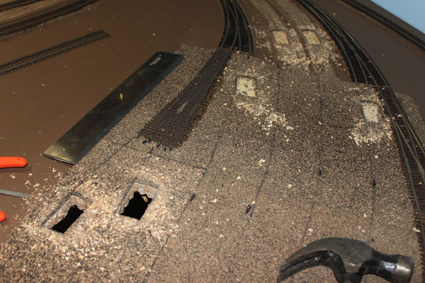
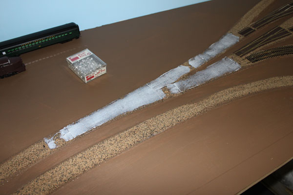
Here I am cutting out the openings for the Kadee under track electromagnets. These will be used to uncouple the engines from the coaches as an alternative to manual uncoupling using a pick. (7/4/10)
28 coaches sit in the completed yard. Thin styrene plates cover the electromagnets to keep future ballast from falling through. The engine service tracks are at the bottom of the photo. (7/4/10)
The coach yard from the entrance end. Considering the large amount of compression I had to work in, I'm generally happy with the way it turned out. (7/9/10)
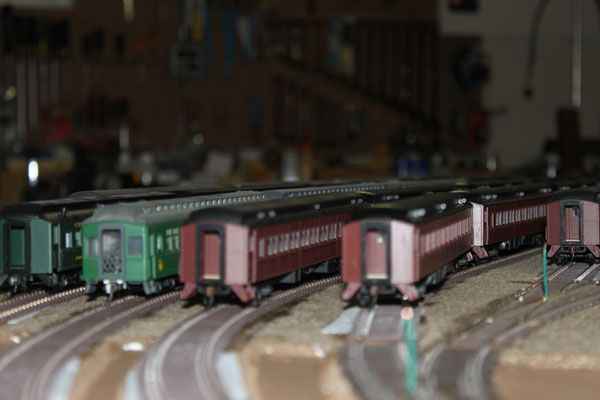
The old Athearn blue box coaches in the foreground are actually on the loop running track and wouldn't be stored here. (7/9/10)
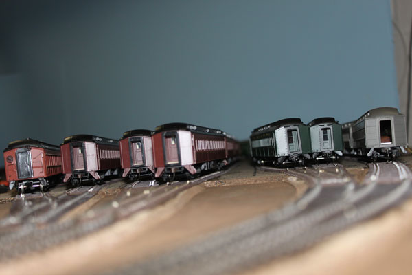
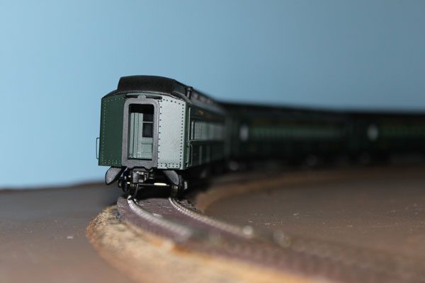
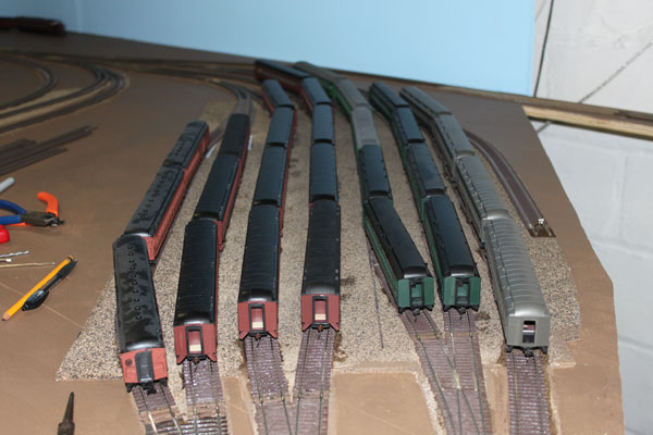
A ground-level view of the PRR and CNJ commuter coaches in the unfinished yard. (7/9/10)
Another view of the opposite side of the yard. Notice the frog feeder wires. (7/9/10)
A PRR BP20 Shark sits in the yard. The green feeder wire will be soldered to the turnout frog here and on the other eleven frogs in the yard. (7/9/10)
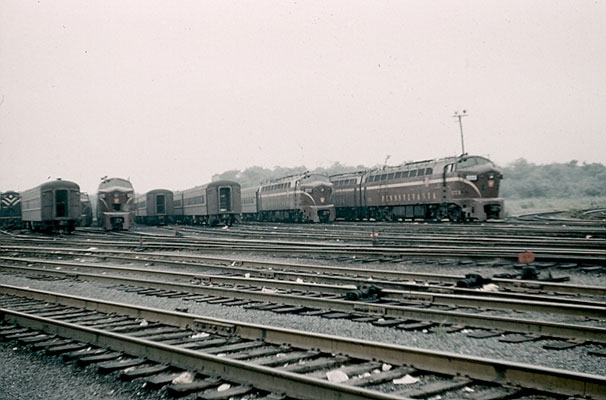
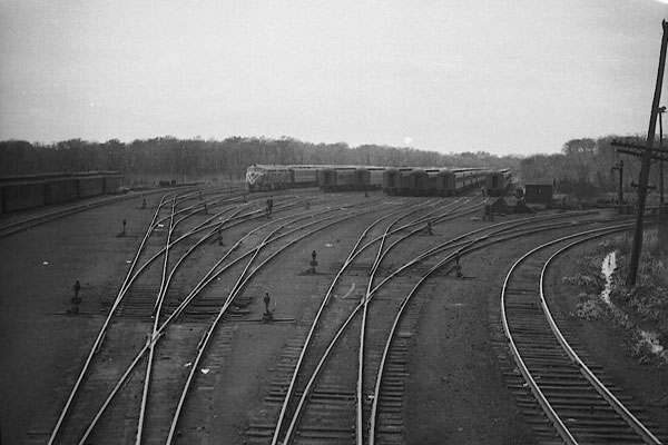
Here is the prototype in the late 1950s with several PRR sharks and a CNJ Trainmaster waiting to depart for the trip north to New York and Jersey City. (7/9/10)
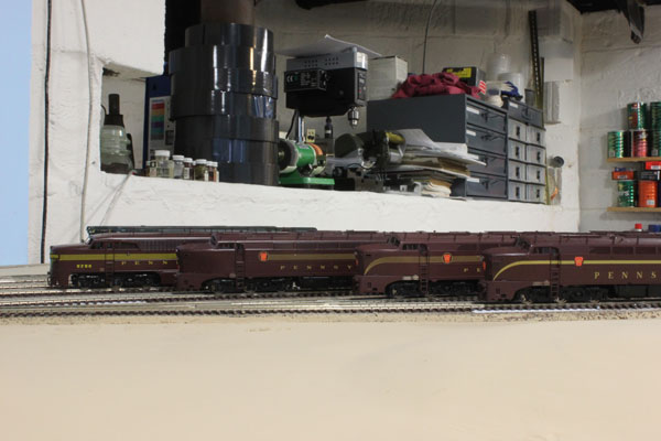
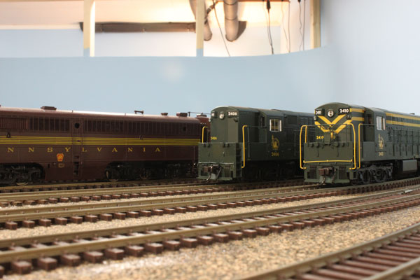
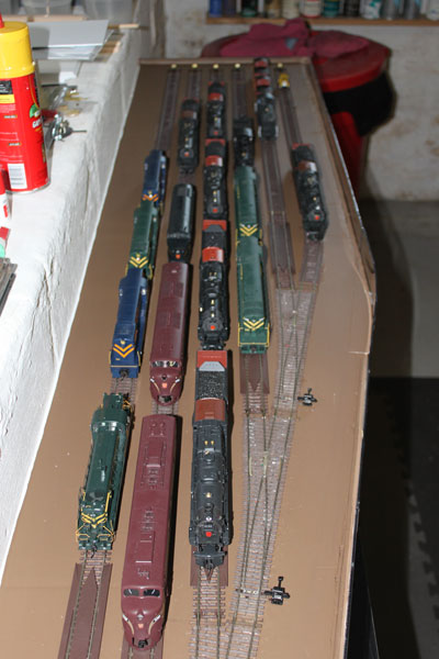
Three Baldwins and an Alco sit in the Bay Head yard. In the background are rolls of camper foam tape to be used under the mainline cork roadbed for height and sound deadening. (7/12/10)
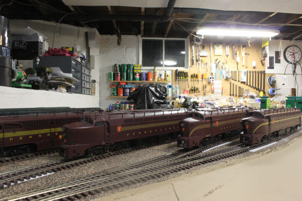
These brass BP20 Baldwin sharks and Alco PA (left) are all Oriental Limited models waiting to be upgraded with corrected markings, dcc and sound. (7/12/10)
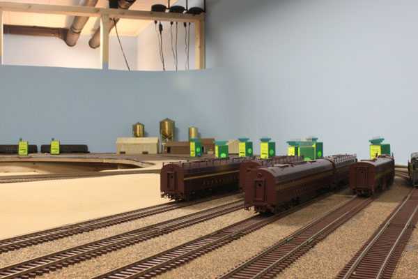
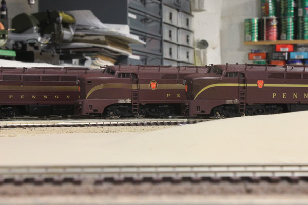
The Pennsy diesel fleet from the rear (south) end of the coach yard. (7/12/10)
A couple of Atlas CNJ Fairbanks-Morse Trainmasters idle on the CNJ holding tracks. (7/12/10)
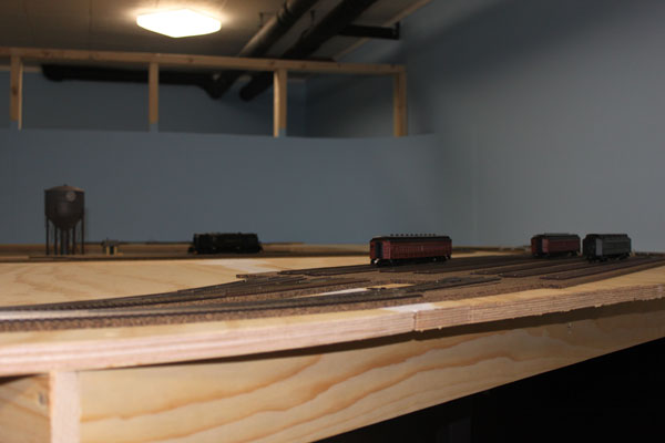
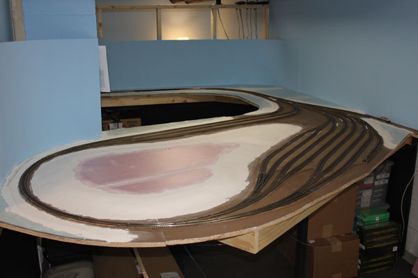
If you haven't noticed, I've jumped ahead a bit here showing the completed landform in the center of the loop. Construction of this will follow in the next photo set. (7/12/10)
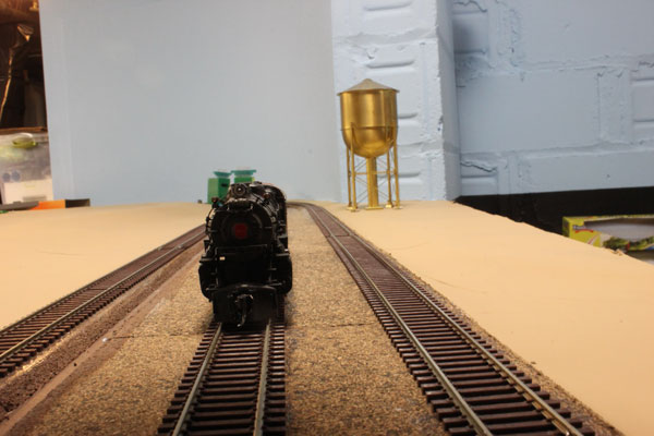
A Broadway Limited K4s Pacific sits alone in the engine servicing area. The brass water tank is a Railworks Ltd. 100,000 gallon tank. (7/12/10)
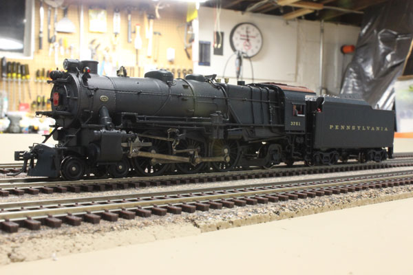
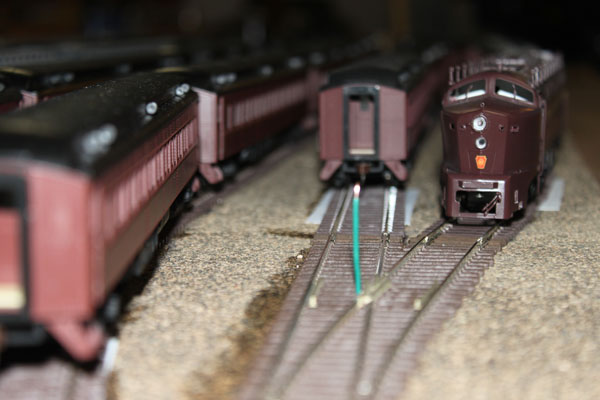
Broadway Limited PRR K4s #3751 waits on the holding track for its next assignment (7/12/10)
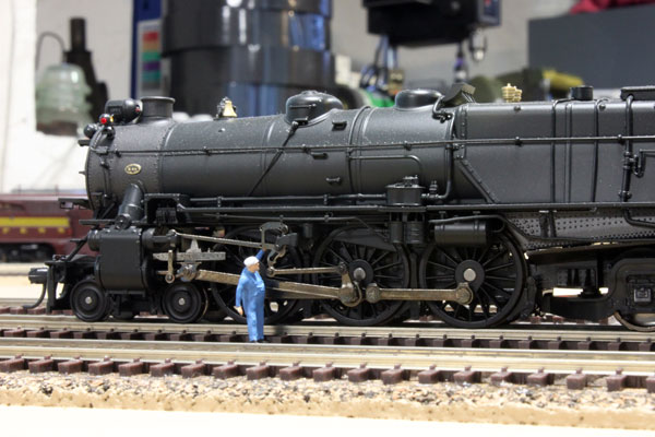
The running gear is checked before the next departure to South Amboy. (7/12/10)
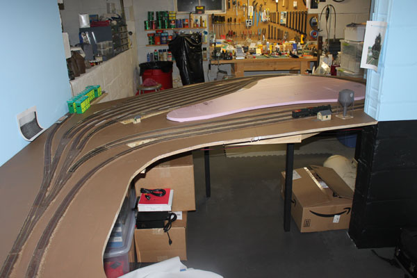
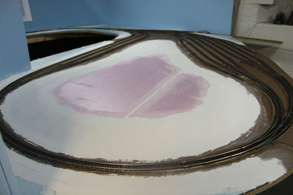
I finally reached the point where I could dig into some scenery construction! The base for the woods in the center of the loop takes form with 1 inch foam board cut out to the approximate boundary of the forest tree line. (7/16/10)
I had to splice two pieces of foam together to make the forest base. I also cut away the sharp corners of the cork sheet roadbed under the coach yard that were not required. Now where did I store my hot wire foam cutter? (7/16/10)
I did a test of cutting/shaping the foam on a small triangular piece, shown here. The black lines trace the outline of a small stream running under the center of the yard from the woods. (7/16/10)
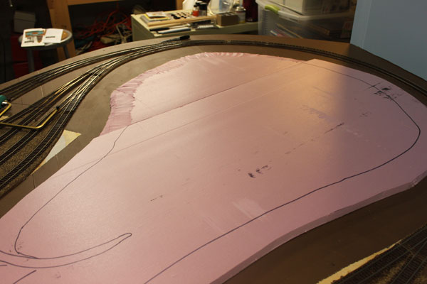
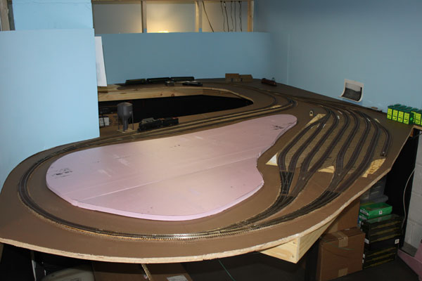
Once I got the hang of foam cutting, I drew a line along the perimeter approximating the top of the forest rise. (7/16/10)
I went back and shaped and re-shaped the edges several times before it was right. The foam will now make a good base for the planting of the pine/oak/maple forest in the center of the loop, which is one of the few remaining untouched natural forests left in NJ this close to the shore. (7/16/10)
Meanwhile, on the other end of the construction, the double track main line is loosely positioned on the shelf. The siding to the right is for the Makin Manufacturing Plant, makers of concrete block. This business was located at Washington Avenue in Point Pleasant Beach. (7/16/10)
After I was satisfied with the alignment of the mainline, I was finally able to put the foam camper tape to use. It was easy to work with and conveniently raised the mainline to the proper height compared to the adjacent sidings. The sound deadening is great too! (7/16/10)
I included this photo to show how the back end of the Bay Head loop looked. This is a CNJ excursion (Camelback 774) in 1954. Notice the proximity of the woods in the center of the loop (left). (7/16/10)
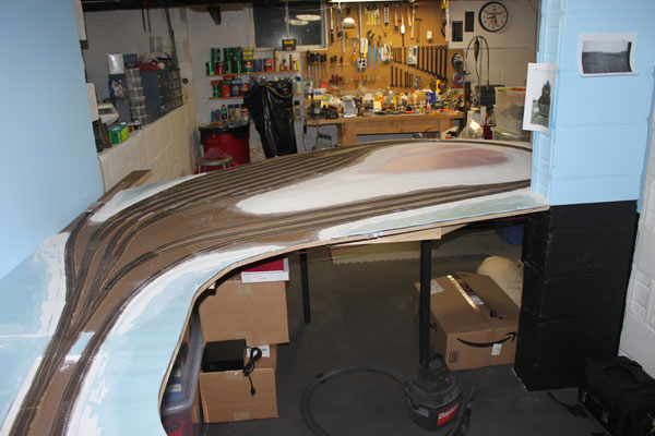
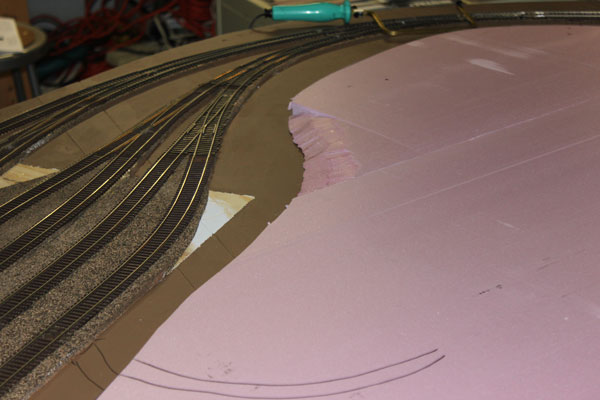
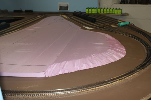
After working further with the 1 inch foam in the center of the loop, I glued down 1/4 inch blue foam sheeting along the adjacent track r.o.w. This allowed me to form a drainage ditch along the tracks while providing a good scenery base. (7/22/10)
The blue foam continues out of the yard and onto the mainline. I used joint compound to fill in the gaps along the edge of the foam and the roadbed, which worked out quite nice. The road crossing in this photo is Sea Avenue (State Route 35). (7/22/10)
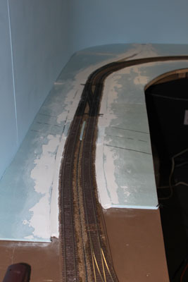
The base for the woods in the center of the loop took a little extra effort. I used several thin coats of joint compound to feather the edges so it wouldn't crack. (7/22/10)
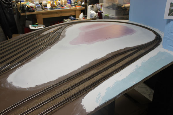
The foam base around the engine servicing tracks also got the same treatment. The blue foam really works nicely when the land is flat with just minor irregularities. (7/22/20)
After the final coat of joint compound dried, it was sanded down to create a gentle slope from the interior of the woods to the edge of the track. (7/22/10)
Although you can't really see it yet, the small stream from the woods, under the coach yard, and into the bay off the layout to the right, was carved and shaped into the foam and mud. (7/22/10)
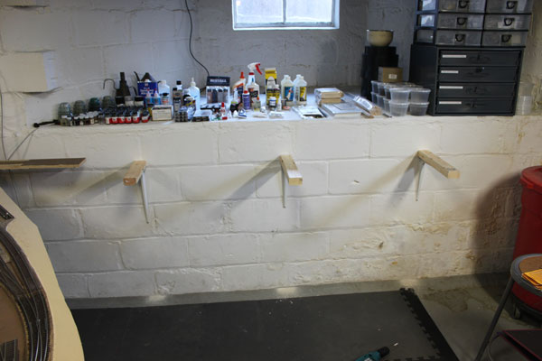
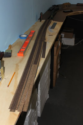
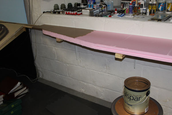
Breaking from the main layout, it was time to construct the small staging/fiddle yard off the Bay head loop using the abandoned PRR Bay Head/Seaside/Pemberton line as an entrance. Here, I used regular steel shelf brackets attached to the block wall with 1x2 wood toppers. (7/28/10)
Since this was a staging yard, I decided to use 2 inch foam insulation board as the base. I didn't want to put too much weight on the wall brackets and I wanted to try out using the foam as a base in layout construction. (7/28/10)
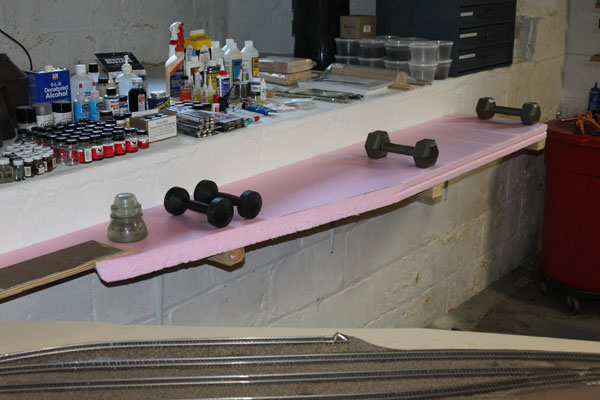
After cutting the foam to the shape I wanted for the yard, while still being able to comfortably reach my modeling supply storage area to the rear, I glued the foam to the 1x2s and the plywood protrusion with Liquid Nails for projects. Worked quite nicely. (7/28/10)
After the adhesive cured for a couple of days, I removed the weights and sealed the joint with the concrete block wall with caulk. Here, a base coat of latex pain is being applied to seal the foam. I found working with the foam board to be a very easy experience. (7/28/10)
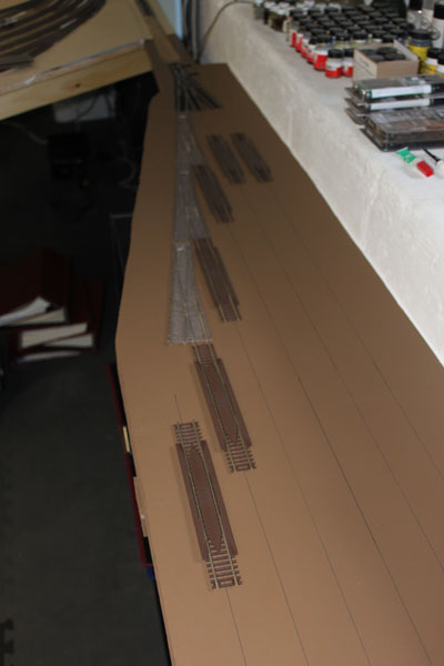
After
painting the foam, I marked out where the yard tracks and turnouts would
go. I used an
Atlas re-railer on each yard track and tried to position everything for
maximum track storage of engines and cars. The ME turnouts here
are all hand-thrown using Caboose Ind. stands. (8/7/10)
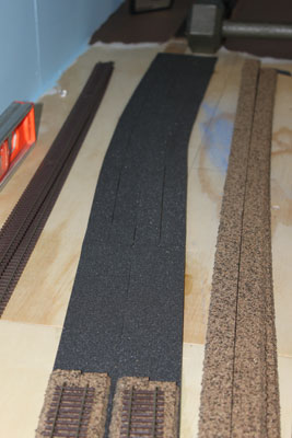
Laying the code 83 track on the foam was pretty basic. I decided not to use roadbed here and glued the track right to the foam surface using adhesive caulk. Track-on-foam is noisy, but it's only a storage yard and not part of the operating layout. (8/7/10)
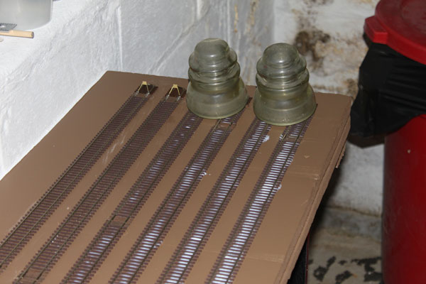
With the track and turnouts glued down, it was time again to wait for everything to dry and cure. Glass telegraph insulators make great weights! (8/7/10)
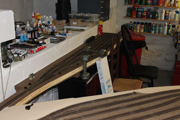
While waiting, I went ahead and attached wood furring along the front of the foamboard using Liquid Nails for projects. Chairs and weights hold it in place until dry. (8/7/10)
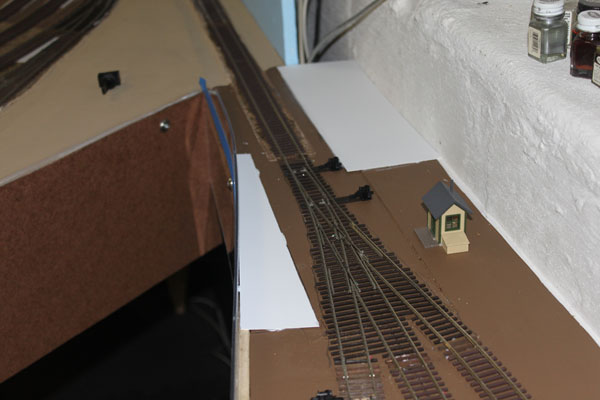
I used some styrene sheets to fill in the open spots at the yard entrance. Against my better judgment, but to maximize space, I used a Walthers 3-way turnout to break out the tracks. Hopefully this won't be a future headache. (8/7/10)
On the edge of the peninsula, I attached sheets of clear acrylic for a fascia. It will be painted below the blue tape and clear for about 2 inches above the foam surface to help protect the rolling stock. The bookcases underneath are a perfect fit. (8/7/10)
I placed some motive power in the yard to check capacity. The track power for the yard can be turned on and off using a toggle switch on the fascia. (8/7/10)
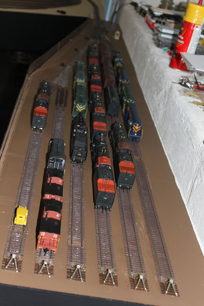
All the tracks and turnouts were tested and given the OK. I'll come back later and do some minimal scenery (cinder/ballast) to give the yard a better look. (8/7/10)
The time had come to build the fascia on the completed parts of the layout. In all honesty, I was eager to give the layout a more finished look. 1/8" hardboard 8 inches wide. (8/10/10)
I used #8 wood screws and flange cups screwed into the plywood top to attach the fascia. I then sealed the fascia edge along the layout with silicone caulk. (8/10/10)
The gap seen here is for the Bay Head loop and yard control panel. Under the layout is a wood spaceship I built back in the early 1980s. A packrat, I am! (8/10/10)
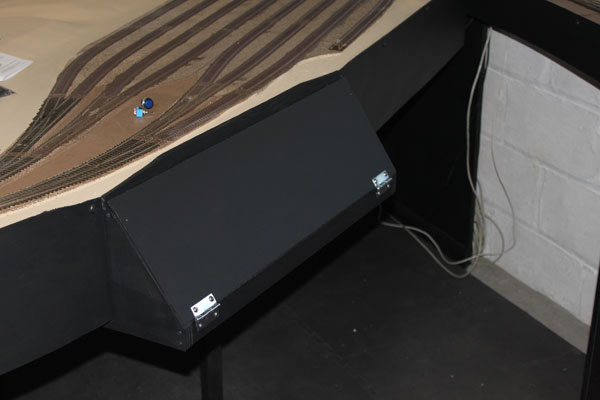
Here is the finished fascia and control panel. I wanted something easy to see and since this area is designed for a dedicated yardmaster, I'm not too concerned about the protrusion. (8/10/10)
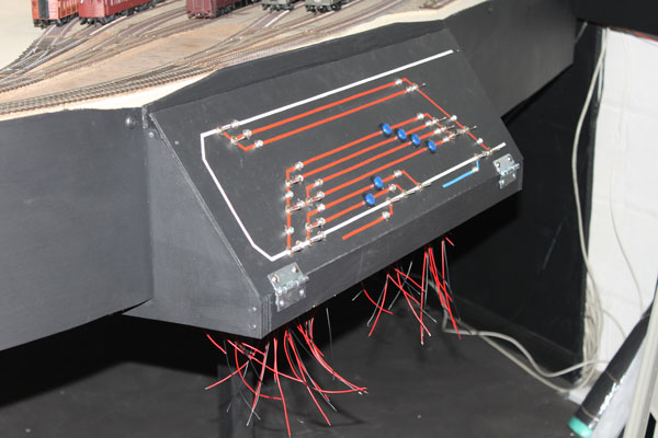
I studied the real track diagrams of the Bay Head loop before coming up with this compromise for the control panel. I plan to have secondary turnout switches on the opposite side of the loop for when the yardmaster is on vacation... (8/10/10)
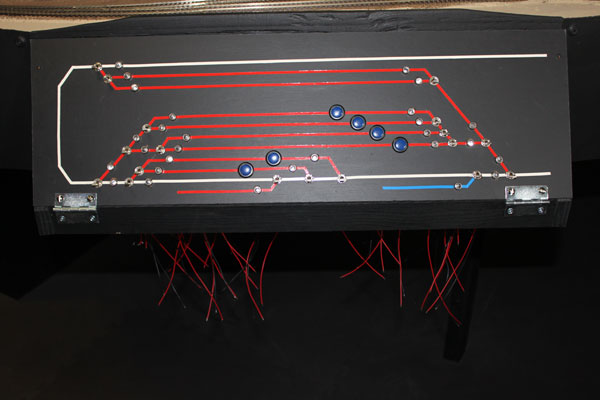
The white line is the main, red is the storage and service tracks. The blue line is the defunct PRR Atlantic Division line to Seaside and Pemberton...my entrance to the staging yard. Toggles with led's for the switches, blue pushbuttons for the electromagnet uncouplers. (8/10/10)
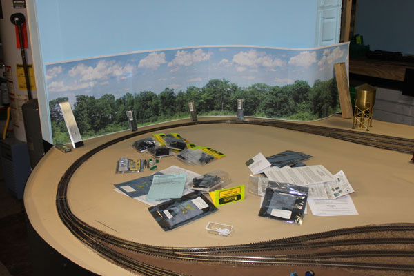
Experimenting with a photo backdrop at the loop. The backdrop consists of about a dozen legal-size printed sheets of paper taped and glued together from SceniKing. (8/15/10)
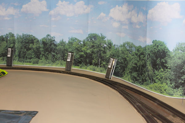
The sheets are only taped together for now so the seams are noticeable. This particular backdrop matches what was really there along the loop pretty darn close. (8/15/10)
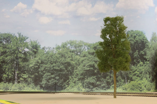
With a foreground tree planted, the still very unfinished loop suddenly looks much more realistic. I plan to use this type of background wherever possible on the layout. (8/15/10)
Putting the preliminary scenery work aside for now, I next tackled construction of the second level over the existing first level of layout. (8/15/10)
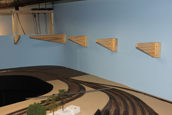
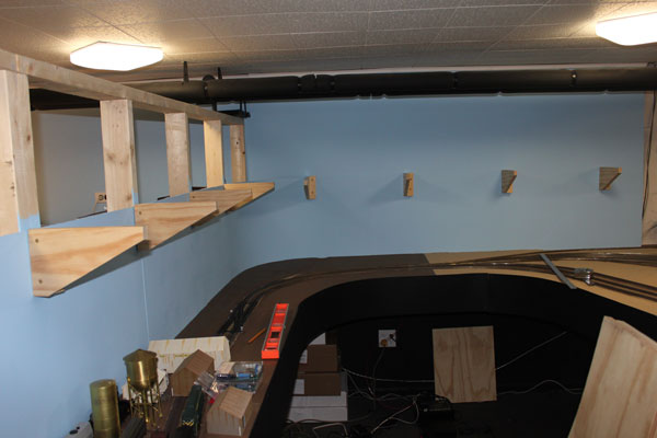
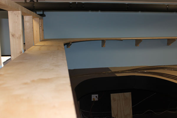
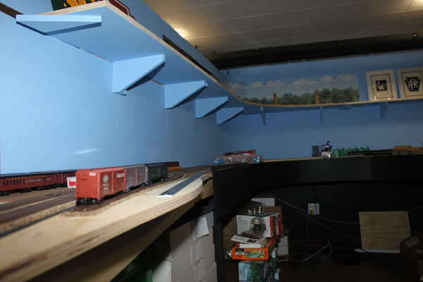
The supports are composed of tapered 1x6 pine attached to a 2x2, which in turn is secured to the wall at each stud behind the sheetrock. Notice the extended support in the corner. (8/15/10)
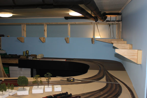
All of the supports are up and the plywood base is next. The upper level of the layout here is 20 inches above the lower level. The supports are very sturdy. (8/15/10)
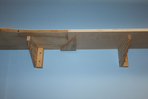
Next came the plywood base for the upper level. I used a simple splice plate of scrap plywood at the joint of each section, seen here. (8/22/10)
The upper level is recessed back about four inches from the lower level here. This part of the layout will be the mainline between Asbury Park and Allenhurst. (8/22/10)
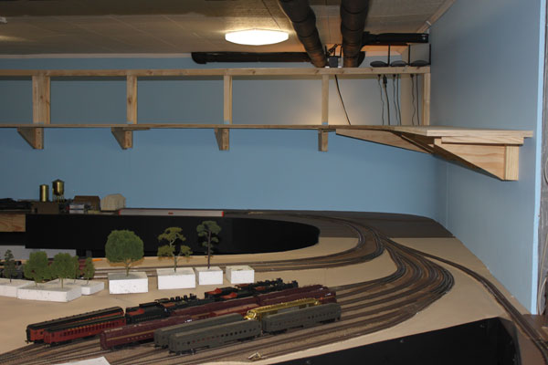
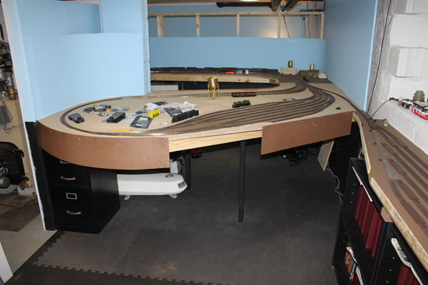
An overview shot of the upper level and its relation with the Bay Head Yard. (8/22/10)
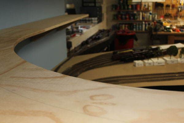
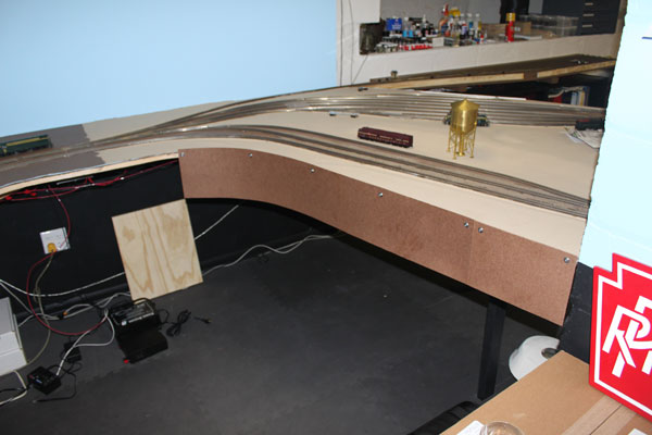
I cut the curvature of the fascia on the upper level to flow with the mainline here (8/22/10)
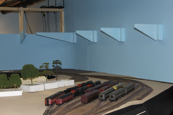
After I was satisfied with everything, I painted the upper level supports with my sky blue paint before permanently attaching the plywood. (8/22/10)
The finished upper level construction from below. Along the front of the supports and behind the fascia will be a row of LED lighting for the lower deck. (8/22/10)